We are now ready to begin rendering 3D scenes. Unlike 2D, which has a direct correlation between world coordinates and screen coordinates, we must project our 3D world onto a 2D screen. The quality of our scenes, however, will depend on preserving some degree of depth of the objects within the world. We can accomplish this through a variety of visual cues such as occlusion (objects being partially blocked by other objects), lighting (object surfaces displaying color gradients), and perspective (the closer the object is, the larger it appears).
We can think of the process of projection as taking a "picture" of the world from a particular location using a camera. The particular camera model we will use is the simplified pinhole camera where the aperature is a single pinhole. Light rays are drawn from every point in the world, through the pinhole, and onto the projection plane (i.e. film). This particular method clearly will have the closest objects along each ray being the ones appearing in the final scene.
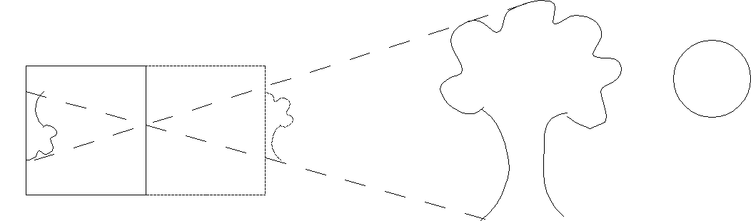
Since this model produces inverted images, we will assume that the projection plane is loacated an equal distance in front of the camera such that our images are right-side up.
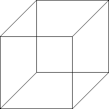
The simplest type of projection is known as orthographic, often used in engineering drawings. In this projection mode, the camera is assumed to be at an infinite distance, i.e. at +∞ looking in the -z direction. Thus all rays become parallel and objects will have the same height as they are in the world with parallel lines remaining parallel. For example, a cube drawn in orthographic projection would appear as (is the cube slanting downward to the left or upward to the right?)
0. Getting Started
Download CS370_Lab07.zip, saving it into the labs directory.
Double-click on CS370_Lab07.zip and extract the contents of the archive into a subdirectory called CS370_Lab07
Navigate into the CS370_Lab07 directory and double-click on CS370_Lab07.sln (the file with the little Visual Studio icon with the 12 on it).
If the source file is not already open in the main window, open the source file by expanding the Source Files item in the Solution Explorer window and double-clicking spinningCube.cpp.
1. 3D Geometry and the Depth Buffer
We define object geometry in 3D in the same manner as in 2D only now with each vertex having 3 components - (x,y,z). We then pass the 3D vertices into the graphics pipeline using the command
glVertex3f(x,y,z);
or
glVertex3fv(*p);
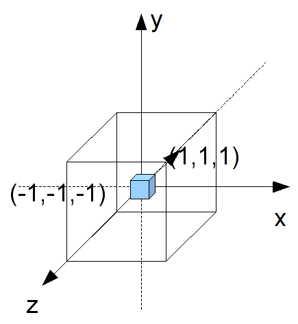
As a natural extension of our 2D world coordinate extents, in 3D space the extents of the rendered scene are [-1,1] for all three axes (we will change these extents later in this lab).
Unlike in 2D where objects were rendered via a Painter's algorithm, i.e. the last object rendered is the one that appears, in 3D we typically want the closest object to be the one that appears. Fortunately, OpenGL provides a way of automatically performing this occusion behavior (also known as hidden surface removal since those surfaces that are hidden behind other ones are removed) through the use of the depth buffer. This buffer keeps track of the depth of the closest object for each rendered pixel. As subsequent objects are rendered, only those whos pixels have a depth less than the current closest one stored in the buffer are rendered (subsequently also updating the depth buffer accordingly). To use the depth buffer, we must tell GLUT to allocate memory for the depth buffer and enable the depth test (which in subsequent labs we will temporarily disable for effects like transparency). To allocate memory, we simply need to add another flag when we initialize the window. For example
glutInitDisplayMode(GLUT_DOUBLE | GLUT_RGB | GLUT_DEPTH);
Then to enable the depth test we issue the command (usually in main() with the other initializations)
glEnable(GL_DEPTH_TEST);
We must also clear the depth buffer every time we render the scene by adding the appropriate flag to the glClear() command at the beginning of the display() function
glClear(GL_COLOR_BUFFER_BIT | GL_DEPTH_BUFFER_BIT);
Finally, when we create 3D geometry, we must be careful to order our vertices properly. Each polygon we create will have a front face and a back face which is defined by the right-hand rule. If we curl the fingers of our right hand to follow the vertex order, our right thumb will point in the direction of the outward normal (i.e. the front face). Furthermore, we can control the rendering of the front and back faces separately such that when we are "outside" the object we see the front faces but when we go "inside" our objects we see the back faces.
Tasks
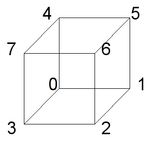
Define the global variable cube[][] with the corners of the cube at the unit vertices, i.e. (± 1, ± 1, ± 1). Note: there are eight vertices that can be defined in the order given in the following picture
Add code to main() to allocate the depth buffer in the glutInitDisplayMode() command, i.e. add the GLUT_DEPTH flag.
Add code to main() to enable the depth buffer via the GL_DEPTH_TEST flag.
Add code to display() to clear the depth buffer via the GL_DEPTH_BUFFER_BIT flag. What happens if you forget to do this?
Add code to render_scene() to draw the cube by calling colorcube().
Add code to colorcube() to render the six faces of the cube by passing the proper vertices and colors to the provided quad() routine (which simply renders a four sided polygon and outlines the border). Note: make sure each face is drawn in a counter-clockwise fashion when looking at that face head on, i.e. correctly define the front face vertex order.
At this point if you compile and run the program you will only see a colored screen as we are looking right at one of the faces.
2. Orthographic Projection and the Reshape Callback
Often it is convienient to define the geometry of the objects in our world without having to scale everything to fit within the default extents of [-1,1]. This will usually produce a visually poor scene (or nothing rendered at all). Thus we want to be able to adjust the viewing volume, i.e. the extents of our rendered world, so that the objects appear and fill the screen as we wish. For orthographic projection, the viewing volume will be a rectangular parallelapiped (rectangular "cube") such that the camera is looking down the z axis in the negative direction.
To change the extents, we will modify the projection matrix which we must first select using the command
glMatrixMode(GL_PROJECTION);
We then set the extents of our viewing volume using the command
glOrtho(GLdouble left, GLdouble right, GLdouble bottom, GLdouble top, GLdouble near, GLdouble far);
where left and right are the x extents, bottom and top are the y extents, and near and far are the z extents. These values are measured from the camera whose default position is the origin (thus for now these values are the world extents).
Finally after setting the new extents we normally want to switch back to the model-view matrix (which is where the object transformations will be performed) using
glMatrixMode(GL_MODELVIEW);
The usual place to modify the projection matrix, i.e. set the viewing volume, is in the reshape callback. This callback is called whenever the window is resized (including when it is first created) and is registered similarly to the other callbacks with
glutReshapeFunc(reshape);
The reshape function has the prototype
void reshape(int w, int h);
where w is the new width of the window (in pixels) and h is the new height of the window (in pixels). Using this information, we may wish to adjust our viewing volume via the glOrtho() command to either have the objects stretch to the new aspect ratio (default) or adjust to the smaller dimension but maintain the original aspect ratio. We accomplish the later anisotropic scaling (each axis scales differently) by multiplying the appropriate dimension by the ratio of the larger dimension by the smaller (thus "stretching" the world in the larger dimension such that the object appears with the original proportions). Sample code for anisotropically "scaled" [-1,1] extents would be
void reshape(int w, int h)
{
    GLfloat ratio;

    // Set new screen extents
    glViewport(0,0,w,h);

    // Select projection matrix
    glMatrixMode(GL_PROJECTION);
    glLoadIdentity();

    // Adjust viewing volume (orthographic)
    // If taller than wide adjust y
    if(w <= h)
    {
        ratio = (GLfloat) h/ (GLfloat) w;
        glOrtho(-1.0f,1.0f,-1.0f*ratio,1.0f*ratio,-1.0f,1.0f);
    }
    // If wider than tall adjust x
    else if (h <= w)
    {
        ratio = (GLfloat) w/ (GLfloat) h;
        glOrtho(-1.0f*ratio,1.0f*ratio,-1.0f,1.0f,-1.0f,1.0f);
    }

}
Tasks
- Register the reshape callback function reshape in main().
- Add code to reshape() to perform anisotropic scaling, i.e. preserving the original aspect ratio of the objects, for "scaled" world extents [-2.0,2.0] for all three axis. Note you should now see the cube rendered in the center of the screen. What happens if you replace the glOrtho() commands with ones that have fixed extents (i.e. without the ratio multiplication) and then resize the window?
- Add code to display() to select the modelview matrix and initialize it to the identity. NOTE: This should be done before calling render_scene() to ensure any prior transformations are removed.
- Add code to render_scene() to rotate the cube about the (1.0,1.0,1.0) axis by an angle theta.
As in the previous lab, spacebar will toggle the animation.
Compiling and running the program
Once you have completed typing in the code, you can build and run the program in one of two ways:
- Click the small green arrow in the middle of the top toolbar
- Hit F5 (or Ctrl-F5)
(On Linux/OSX: In a terminal window, navigate to the directory containing the source file and simply type make. To run the program type ./spinningCube.exe)
The output should look similar to below
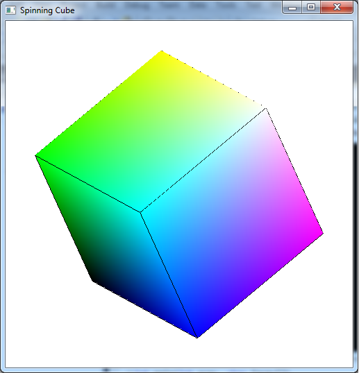
To quit the program simply close the window.
At this point we are now able to render 3D geometry and adjust the world extents to only render the portions of the world that we desire. Furthermore, all the 2D transformations that we learned in previous labs directly apply to 3D geometry. In particular, instance transformations are a valuable technique for creating complicated scenes using simple template objects defined about the origin. In the next lab we will extend our camera model to provide perspective views which when done properly appear more like a real picture (but when done wrong can be a total disaster).
