Orthogonal projection is typically used when the camera is at a fixed location and the objects are manipulated through transformations. By duality, however, (or Einstein relativity) it does not matter whether the camera is fixed and the objects move or the objects are fixed and the camera moves (and frequently the objects and camera will both move). Particularly with perspective projection, the camera location will play an important role since the viewing volume will be defined relative to the camera's location and orientation. Fortunately, OpenGL allows us to define the objects in world coordinates and then simply place the camera at the desired location without worrying about all the underlying projection transformations.
Since we will now start rendering scenes with many objects (particularly based on the same instance object), performance in terms of rendering efficiency can become an issue. In particular, for complex geometry with a large number of vertices, the overhead incurred via the glVertex3f() function calls incurs a substantial performance penalty. We can mitigate this problem by loading the vertices onto the graphics card and then simply telling the card to render the objects (rather than repeatedly pushing all the data down the pipeline). The disadvantage to this approach is that once the vertices are on the graphics card, they cannot be modified by the application (other than by modelview transformations).
0. Getting Started
Download CS370_Lab08.zip, saving it into the labs directory.
Double-click on CS370_Lab08.zip and extract the contents of the archive into a subdirectory called CS370_Lab08
Navigate into the CS370_Lab08 directory and double-click on CS370_Lab08.sln (the file with the little Visual Studio icon with the 12 on it).
If the source file is not already open in the main window, open the source file by expanding the Source Files item in the Solution Explorer window and double-clicking perspectiveCubes.cpp.
1. Perspective Projection
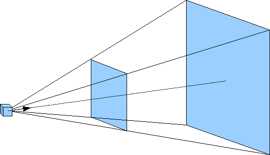
Unlike orthogonal projection where parallel lines remain parallel and the size of an object is independent of its location relative to the camera, perspective projection is more akin to actual scenes. For example, two parallel railroad tracks appear to converge to a point in the distance and as objects move away from the observer, i.e. the camera, they get smaller in size. For this projection mode, rather than the viewing volume being a parallelapiped, it has a shape known as a frustum. This frustum can be visualized as a pyramid with its point at the camera but starting a small distance from the camera (the near clipping plane) and extending a further distance outward (the far clipping plane) as shown below.
For this projection mode, the projection plane (i.e. camera film) is the near clipping plane. The frustum is defined by modifying the projection matrix via the command
glFrustum(GLfloat left, GLfloat right, GLfloat bottom, GLfloat top, GLfloat near, GLfloat far);
where again left and right are the x extents of the near clipping plane, bottom and top are the y extents of the near clipping plane, and near and far are the z extents in world coordinate units of the near and far clipping planes respectively. These values, however, are measured from the camera whose default position is the origin looking back down the z axis. However since the camera now is within the scene, near must be positive and far > near (be careful not to make near too small). Also depending on the location and orientation of the camera, these values typically do not refer to world coordinate extents, but to extents relative to the camera.
Tasks
- Add code to keyfunc() to set the projection flag proj to ORTHOGRAPHIC for 'o' and PERSPECTIVE for 'p'. This will allow you to toggle between projection modes via the keyboard.
- Add code to display() to set an orthographic projection (via glOrtho()) if proj is set to ORTHOGRAPHIC with extents (-4,4,-4,4,1,8). NOTE: Be sure to switch to the projection matrix and load the identity before setting the projection transformation.
- Add code to display() to set a perspective projection (via glFrustum()) if proj is set to PERSPECTIVE with extents (-1,1,-1,1,1,8). NOTE: Be sure to switch to the projection matrix and load the identity before setting the projection transformation.
- Add code to display() to select the modelview matrix and initialize it to the identity matrix prior to calling render_scene() (but after the projection matrix has been set).
2. Camera Position
The default camera position is at the origin pointed in the -z direction. We can, however, change this position and orientation with the command
gluLookAt(eyex, eyey, eyez, atx, aty, atz, upx, upy, upz);
where eyex, eyey, and eyez are the world coordinates of the camera; atx, aty, atz are the world coordinates where the camera is pointing; and upx, upy, upz define a vector indicating which direction is up for the camera (since otherwise the camera could have any orientation about the axis defined by eye and at). Since this command essentially creates an initial global transformation, it should be issued prior to any other modelview transformations (otherwise the camera location and orientation will be concatenated with any preceeding transformations). Note: Usually this command will be placed at the beginning of render_scene() just after the initial glLoadIdentity().
Tasks
- Add code to display() to set the camera vectors via the gluLookAt() command. Use the global arrays eye[], at[], and up[] along with the symbolic constants X, Y, and Z given at the top of the code. NOTE: Make sure to do this after you initialize the modelview matrix to the identity matrix but before you render any objects (such that all objects will be in the frame of reference of the camera).
3. Display Lists
Depending on our requirements, one way to improve performance is through the use of display lists. If the geometry of our object(s) is fixed (for example with instance objects) we can compile the geometry into a display list and store it on the graphics card. Then when we wish to use the object(s), we simply tell the graphics card to render the desired list (thus avoiding passing any geometry from the application to the pipeline). However since the object(s) is compiled, once created it cannot be modified (unless it is subsequently recompiled). The display lists may contain multiple objects, even using different instance transformations for each object, as long as the local transformations are static, i.e. we cannot modify any internal transformation parameters after the list is compiled.
In order to use display lists, we must perform three tasks. First we will define a symbolic constant to identify the list. Second we will create the display list using the standard geometry commands (including transformations) that we have previously learned. Usually this is done when we initialize GLUT, i.e. we do not want to do this in the display() callback (which would recreate the display lists every time the scene is rendered). Then finally we will execute the list within render_scene() whenever we wish to render the objects.
Defining a symbolic constant
To identify each list, we want to define a unique unsigned integer via a #define statement (i.e. symbolic constant) at the top of the program. This will provide a convenient way of distinguishing our lists while making our code more readable.
Creating a display list
To create a display list (usually in a separate initialization function) we use a structure similar to:
glNewList(listname, GL_COMPILE);
    // Save the current state
    glPushAttrib(GL_CURRENT_BIT);

    // Insert graphics code here

    // Restore the previous state
    glPopAttrib();
glEndList();
where listname is the symbolic constant for the list and GL_COMPILE tells OpenGL to compile the list (and load it onto the graphics card). Between the glNewList() and glEndList() commands, typically the first and last commands are glPushAttrib(GL_CURRENT_BIT) and glPopAttrib() to save and restore all state information prior to rendering the list (so that any transformations within the list do not affect subsequent rendered objects). Any valid geometry commands including glBegin(), glEnd(), glVertex*(), and any transformations can be used to create the list. NOTE: Variables may be used within the geometry commands, however only their current values will be used to create the list and hence any subsequent modification of the variables (e.g. in the idle() callback) will not affect the list object (unless the object is subsequently recompiled by calling the list creation function).
Since the lists can consume memory on the graphics card (which may be needed for other things like texture maps and shader programs), when a list is no longer needed it can be deleted using the command:
glDeleteLists(listname, 1);
where listname is the name of the list to delete and 1 specifies to delete a single list.
Executing a display list
At any point in render_scene() that we wish to render the objects from a display list, we can use the command
glCallList(listname);
where listname is the name of the list we wish to render. NOTE: The objects will be subject to any transformations currently in the modelview transformation matrix.
Tasks
- Add code to main() to call create_lists() to execute the display list creation function. NOTE: This is done before the graphics loop is entered since it should be done only once.
- Add code to create_lists() to build the display list CUBE by calling the function colorcube() within the list creation structure given in this section. NOTE: Remember to store and retrieve the current state when creating the list.
See section 3.12.1 of OpenGL: A Primer for information on manipulating multiple display lists using a single command.
4. Rendering Multiple Objects
We have already discussed in previous labs how to reset the modelview matrix using glLoadIdentity(). However often we wish to maintain a global transformation, e.g. one produced by positioning the camera, for all objects in the scene while still allowing for local transformations on a per object basis. Fortunately OpenGL provides a matrix stack that can be used to push and pop the current modelview matrix as needed. This is done with the commands
// Push the current transformation matrix onto the stack
glPushMatrix();

// Perform any additional local transformations
// and render the object

// Restore the prior transformation matrix
glPopMatrix();
glPushMatrix() places a copy of the current modelview matrix onto the stack prior to any additional local transformations. Once the object is complete, rather than needing to undo the transformations, glPopMatrix() simply sets the modelview matrix to the one at the top of the stack, i.e. the one prior to the recent local transformations. Later we will see how to use the stack to store multiple modelview transformation matrices in order to render a scene using a scene graph.
Tasks
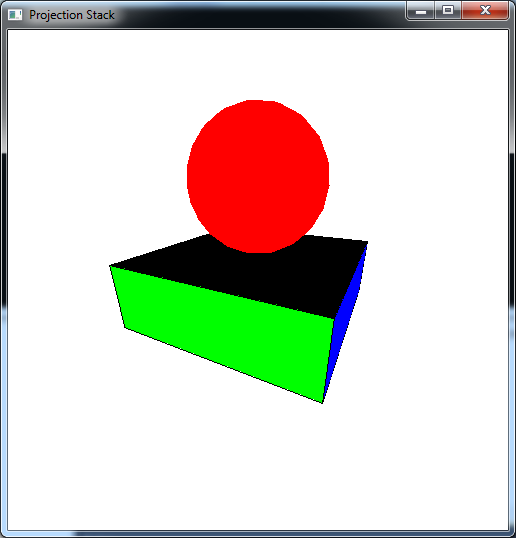
- Add code to render_scene() to render a scaled (by (1.5,0.5,1.5)) cube using the CUBE display list. NOTE: Be sure to save and restore the modelview matrix when rendering this object.
- GLUT (and GLU) provide functions to draw many common geometric shapes such as cubes, spheres, disks, etc. - see sections 4.3 and 4.7 of OpenGL: A Primer for more details. Add code to render_scene() to render a red sphere using glutSolidSphere() of radius 1 with 20 slices and 20 stacks. Translate the sphere up by 1.5 such that it sits on top of the base drawn in the previous step. NOTE: Be sure to save and restore the modelview matrix when rendering this object.
5. Spherical Coordinates
Often times when we wish to move the camera through a scene, simply adjusting the (x,y,z) components in Cartesian coordinates is awkward for the user. Instead it is more natural if the camera is moved in spherical coordinates which consist of an azimuth angle (rotation about the y axis), an elevation angle (rotation down from the y axis), and a radius (distance from the origin), see the diagram below
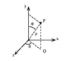
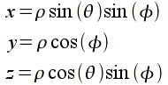
With this coordinate system, the user appears to rotate around the object (azimuth), "over/under" the object (elevation), and "towards/away from" the object (radius). However, since OpenGL strictly uses Cartesian coordinates (i.e. (x,y,z)) the conversion from spherical to Cartesian coordinates is given by
Tasks
- Add code to keyfunc() to allow 'a' and 'd' to adjust the azimuth by adding/subtracting daz. NOTE: The azimuth angle should be bounded in the range [0,360] via wrapping.
- Add code to keyfunc() to allow 'w' and 's' to adjust the elevation by adding/subtracting del. NOTE: The elevation angle should be bounded in the range [0,180] via clamping.
- Add code to keyfunc() to allow 'x' and 'z' to adjust the radius by adding/subtracting dr. NOTE: The radius should not be allowed to go below min_radius.
- Add code to keyfunc() to compute the Cartesian coordinates for eye[] from azimuth, elevation, and radius. NOTE: You will need to convert the angles from degrees to radians in the math functions sin() and cos() using the symbolic constant DEG2RAD.
- To keep the scene from jumping when the first key is pressed, add code to main() to also compute the Cartesian coordinates for eye[] (and typically at[] if it depends on eye[]) from azimuth, elevation, and radius. NOTE: You will need to convert the angles from degrees to radians in the math functions sin() and cos() using the symbolic constant DEG2RAD.
Compiling and running the program
Once you have completed typing in the code, you can build and run the program in one of two ways:
- Click the small green arrow in the middle of the top toolbar
- Hit F5 (or Ctrl-F5)
(On Linux/OSX: In a terminal window, navigate to the directory containing the source file and simply type make. To run the program type ./perspectiveCubes.exe)
The output should look similar to below
To quit the program simply close the window.
Now that we have completed 3D geometry along with the two basic projection modes, we are ready to begin embellishing our scenes by adding effects such as lighting and texture mapping.
