Now that we have completed creating 3D geometry, we would like to enhance our scenes through the application of shadowing caused by lighting. To do this we will use a simple (but somewhat unrealistic) lighting model known as the Phong model. This model consists of defining four material properties, three corresponding light source properties, and some additional geometry parameters controlling the interaction of the two. Unfortunately because the pipeline contains no global information, i.e. once an object is passed through the pipeline any world information regarding it is lost, we are only able to apply lighting on a per object basis. While this provides for some lighting effects, the pipeline is not able to handle reflections amongst objects. Thus a shiny object will not (for now) appear to be reflecting any other objects in the scene.
0. Getting Started
Download CS370_Lab12.zip, saving it into the labs directory.
Double-click on CS370_Lab12.zip and extract the contents of the archive into a subdirectory called CS370_Lab12
Navigate into the CS370_Lab12 directory and double-click on CS370_Lab12.sln (the file with the little Visual Studio icon with the 12 on it).
If the source file is not already open in the main window, open the source file by expanding the Source Files item in the Solution Explorer window and double-clicking basicLightCube.cpp.
If the header files are not already open in the main window, open the header file by expanding the Header Files item in the Solution Explorer window and double-click materials.h and lighting.h.
If the shader files are not already open in the main window, open the shader files by expanding the Resource Files item in the Solution Explorer window and double-click lightvert.vs and lightfrag.fs.
1. Materials
The basic model we will be using for lighting is known as the Phong model. In this model, every surface has a particular material associated with it. This material is defined by four properties
- Ambient - overall background illumination
- Diffuse - scattered light based on the "smoothness" of the surface
- Specular - highlights based on the "shininess" of the surface
- Shininess - the degree of concentration of the specular highlights
Each of the first three properties is defined by a four element array with one component of each array per color channel. These values indicate the percent of the incident light channel that is reflected, hence the higher the value the more the object will appear to have that color. The last property, shininess, is simply a floating point (GLfloat) value. Typically we will create a structure in a header file (materials.h) to define a particular material as follows
struct MaterialType {
    GLfloat ambient[4];
    GLfloat diffuse[4];
    GLfloat specular[4];
    GLfloat shininess;
};
We then add materials (also typically in materials.h) by defining new instances of this structure, for example
MaterialType brass = {
    {0.33,0.22,0.03,1.0},
    {0.78,0.57,0.11,1.0},
    {0.99,0.91,0.81,1.0},
    27.8};
Rather than set a color for an object, we instead apply a material on a per surface (polygon) basis (again materials are state variables that once set are applied to all subsequent polygons until it is changed) using
glMaterialfv(face,property,values);
for the arrays where face is the face we are setting (GL_FRONT, GL_BACK, or GL_FRONT_AND_BACK), property is the property we are setting (GL_AMBIENT, GL_DIFFUSE, or GL_SPECULAR), and values is the appropriate field from the material structure we wish to use.
We set the shininess value using the similar command
glMaterialf(face, property, value);
where face is the same as above, property is GL_SHININESS, and value is the shininess field from the material structure.
Rather than continually setting all the properties individually each time we wish to select a material, we will instead use a setter function that I've included in materials.h
void set_material(GLenum face, MaterialType *material);
which takes as arguments the face that we want to set the material for (identical constants as above) and a MaterialType structure by reference (i.e. you will need the &) to set.
Note that these material properties are passed to the shader through the uniform variable gl_FrontMaterial for GL_FRONT surfaces and gl_BackMaterial for GL_BACK surfaces. Both of these shader variables are of type gl_MaterialParameters (refer to the GLSL Quick Reference).
Tasks
- Add code to materials.h to create a material called brass using the property values given above.
- Add code to main() to set the front and back face with the initial material brass using the set_material() function. NOTE: Remember to pass a structure by reference you need to use the argument &brass.
2. Light Sources
Similar to materials, each light source is defined by three properties - ambient (background), diffuse (scattered), and specular (focused). Again, each of these properties is specified using a (4 component) RGBA color array. The RGB channels describe the intensity for each color channel of the light source, e.g. (1,1,1) would produce white light. For now we will again simply set the alpha channel to 1.
Just as with setting materials, to simplify working with light sources I've provided another structure called LightType that encapsulates these three properties as such:
struct LightType {
    GLfloat ambient[4];
    GLfloat diffuse[4];
    GLfloat specular[4];
};
For example, we can create a white_light that has no ambient but full diffusive and specular components using the following declaration
LightType white_light = {
    {0.0,0.0,0.0,1.0},
    {1.0,1.0,1.0,1.0},
    {1.0,1.0,1.0,1.0}};
OpenGL provides for at least eight light sources enumerated by symbolic constants GL_LIGHT0, GL_LIGHT1, etc. We then specify the properties of the lights we wish to use with the command
glLightfv(source, property, *values);
where light is the light source symbolic constant (GL_LIGHT0, etc.), property is the property to set (either GL_AMBIENT, GL_DIFFUSE, or GL_SPECULAR), and values is the appropriate field from the LightType structure. Rather than set each property separately, I've provided a setter function in lighting.h that will set all three properties based on a passed structure
void set_light(GLenum source, LightType *light);
which takes as arguments the source that we want to set and a LightType structure by reference.
Note that these light source properties are passed to the shader through the uniform array gl_LightSource[ ]. Each element of this array is of type gl_LightSourceParameters (refer to the GLSL Quick Reference).
Tasks
- Add code to lighting.h to create a material called white_light using the property values given above.
- Add code to main( ) to set GL_LIGHT0 to white_light using the set_light( ) function. NOTE: Remember to pass a structure by reference you need to use the argument &white_light.
To turn light sources on/off we will need to pass an array of boolean flags to the shader.
3. Surface Normals
The Phong model computes the contribution of each lighting component (on a per channel basis) based on the relationship between four vectors as shown below
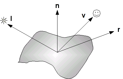
where the four vectors are as follows:
- l is a vector in the direction of the light source
- n is the outward surface normal
- v is a vector in the direction of the viewer (i.e. camera)
- r is a vector in the direction of the reflected light (i.e. at the same angle with respect to the normal as the incident light)
These vectors determine the final intensity of the diffusive and specular lighting components that are applied to the surface.
Ambient Reflection
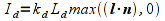
The ambient reflection component is independent of the normals and can be thought of as an overall uniform illumination of the surface. Thus it is simply the product of the incident intensity with the material's ambient array components

where ka is the material ambient component (per color channel), La is the incident ambient light intensity, and Ia is the final ambient light intensity per color channel.
Diffuse Reflection
The diffuse reflection component is based on Lambert's law which states that the more directly the light shines on the surface, the brighter it will appear. Mathematically this is computed using the dot product between l (the light direction) and n (the surface normal). When these two vectors are parallel (light shining directly onto surface), the dot product is one and hence there is maximal diffusive illumination. When the two vectors are perpendicular (light shining across surface), the dot product is zero and hence there is no diffusive illumination. Hence the formula based on the material's diffusive array components is
where kd is the material diffusive component (per color channel), Ld is the incident diffusive light intensity, (l ⋅ n) is the Lambert factor (clipped to a minimum value of 0), and Id is the final diffusive light intensity. This formula can also be extended to account for the attenuation due to distance the object is from the light source.
Specular Reflection
The specular reflection component is used to create highlights on an object (particular for shiny materials). These reflections will be greatest when the reflected light (which depends on the surface normal and the direction of the light source) is in the direction of the viewer. Mathematically this is computed using the dot product between r (the reflected light direction) and v (the viewer direction). When these two vectors are parallel (viewer looking directly at reflection), the dot product is one and hence there is maximal specular illumination. When the two vectors are perpendicular (viewer looking across reflection), the dot product is zero and hence there is no specular illumination. The shininess property determines how focused the highlight is, a high shininess coefficient creates a small bright spot whereas a low shininess coefficient creates a broader less bright spot. The formula based on the material's specular array components is
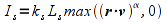
where ks is the specular component (per color channel), Ls is the incident specular light intensity, (r ⋅ v) is the specular factor (clipped to a minimum value of 0), α is the shininess exponent for the material, and Ls is the final specular light intensity. An attenuation factor can also be applied to this component to account for the distance between the object and the light source.
Phong model
The final intensity of each color channel is then simply the sum of the three reflection components as given by (not including attenuation)

Since both the diffusive and (indirectly) specular components depend on the orientation of the surface with respect to the light source, to use lighting we must associate a normal with each vertex in our geometry (since OpenGL works with vertices rather than normals). The normal is assigned using the command
glNormal3f(nx,ny,nz);
or
glNormal3fv(*n);
where (nx, ny, nz) are the components of the normal vector or n is a three element array containing the components.
Note that the normal is passed to the shader through the vec3 variable gl_Normal (refer to the GLSL Quick Reference).
One issue we must be careful of is that all the vectors used in the Phong model are unit vectors, i.e. have unit length. Rather than doing this in the application, we can do this in the shader using the normalize( ) function (refer to the GLSL Quick Reference).
If our polygon is (relatively) flat, then we can simply assign one normal to all the vertices used to define each surface to produce surface normal lighting.
Tasks
- Add code to define the global surface normals normals[ ][3]. Make sure they point perpendicular to the face and are ordered in the array to correspond to the following faces: top, bottom, left, right, front, back.
- Add code to nquad( ) to set the normal on a per face basis, i.e. prior to rendering the polygon, using the parameter n.
4. Shader Lighting
We will implement the lighting calculations in the vertex shader using the shader variables gl_FrontMaterial, gl_LightSource[0], and gl_Normal. The basic light source we will create will be a directional light which produces parallel light rays from an infinite source, e.g. the sun.
First we will write a function that computes the vector dot products using the dot( ) shader function and then multiply it by the light source parameters to get the attenuation of each color channel from the light source. Then in the main shader function we will compute the color by using the material properties.
Tasks
Add code to lightvert.vs in the DirectionalLight( ) function to compute the diffuse dot product nDotVP as the max( ) of 0.0 and the dot() of normal (the normal vector parameter) and the normalize() gl_LightSource[i].position as a vec3.
nDotVP = max(0.0,dot(normal,normalize(vec3(gl_LightSource[i].position))));Add code to lightvert.vs in the DirectionalLight() function to compute the specular dot product nDotHV as the max() of 0.0 and the dot() of normal (the normal vector parameter) and the normalize() gl_LightSource[i].halfVector as a vec3. (see problem 3 of the assignment for a discussion of the half vector).
nDotHV = max(0.0,dot(normal,normalize(vec3(gl_LightSource[i].halfVector))));Add code to lightvert.vs in the DirectionalLight() function to compute the shininess factor pf as 0.0 if nDotVP is 0.0 (i.e. light is perpendicular to the surface) or pow() of nDotHV and gl_FrontMaterial.shininess otherwise.
pf = pow(nDotHV,gl_FrontMaterial.shininess);Add code to lightvert.vs in the DirectionalLight() function to accumulate the ambient with gl_LightSource[i].ambient, diffuse with the product of gl_LightSource[i].diffuse and nDotVP, and specular with gl_LightSource[i].specular and pf.
ambient += gl_LightSource[i].ambient;
diffuse += gl_LightSource[i].diffuse * nDotVP;
specular += gl_LightSource[i].specular * pf;
Add code to lightvert.vs in the main() function to compute normal as the normalize() of the product of gl_NormalMatrix and gl_Normal.
Add code to lightvert.vs in the main() function to compute gl_FrontColor as the sum of all the lighting terms multiplied by the corresponding material properties.
gl_FrontColor = amb * gl_FrontMaterial.ambient + diff * gl_FrontMaterial.diffuse + spec * gl_FrontMaterial.specular;
Compiling and running the program
Once you have completed typing in the code, you can build and run the program in one of two ways:
- Click the small green arrow in the middle of the top toolbar
- Hit F5 (or Ctrl-F5)
(On Linux/OSX: In a terminal window, navigate to the directory containing the source file and simply type make. To run the program type ./basicLightCube.exe)
The output should look similar to below
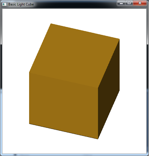
To quit the program simply close the window.
One thing that is apparent from surface normal lighting is the drastic transition of the light effect at edges where the normal is drastically different for multiple adjacent faces. Likewise any large surfaces will have uniform lighting (or awkward lighting based on the tesselation of the surface). Next lab we will see how to generate additional geometry to achieve a more realistic lighting effect. Additionally, we will investigate the other part of effective lighting which is defining other types of light sources.
