In the last lab we introduced basic lighting by creating materials and defining surface normals for our objects using a simple directional light. The light source we created was a single directional light source which was assumed to be at an infinite distance will all light rays parallel and thus striking the object at the same angle, e.g. the sun. While this produced a shading effect as the various faces of the cube rotated into and away from the light source, the effect was not very realistic (particularly considering we had created somewhat reflective materials). To extend the lighting effects, we will now consider how to create different light sources, position them within the scene, and tweak the normals per vertex.
0. Getting Started
Download CS370_Lab13.zip, saving it into the labs directory.
Double-click on CS370_Lab13.zip and extract the contents of the archive into a subdirectory called CS370_Lab13
Navigate into the CS370_Lab13 directory and double-click on CS370_Lab13.sln (the file with the little Visual Studio icon with the 12 on it).
If the source file is not already open in the main window, open the source file by expanding the Source Files item in the Solution Explorer window and double-clicking vertexNormalCube.cpp.
If the header file is not already open in the main window, open the header file by expanding the Header Files item in the Solution Explorer window and double-clicking lighting.h.
If the shader files are not already open in the main window, open the shader files by expanding the Resource Files item in the Solution Explorer window and double-click lightvert.vs and lightfrag.fs.
1. Point Light Sources
Another type of light source that we may wish to add to our scenes is a point light source, e.g. light bulb. This is a local light source, i.e. it has a position in world coordinates, that radiates light omnidirectionally, i.e. equally in all directions. Thus in addition to specifying the color channels for the ambient, diffuse, and specular components, we also will specify a position of the light source (note that this position is represented as a four element array with the last element 1.0). Additionally, we can also incorporate attenuation for these light sources such that the further away from the light source an object is, the dimmer the light will be on that object.
We then set the location property for a point light with the command
glLightfv(source, GL_POSITION, *pos);
where source is the light source symbolic constant (GL_LIGHT0, etc.) and pos is the array containing the position (x, y, z, 1.0). In lighting.h is a utility function that will set all the parameters for a point light
void set_PointLight(GLenum source, LightType *light, GLfloat *position);
which takes as arguments the source that we want to set, a LightType structure by reference for the color channels, and a position array for the location of the light source. (Note there is also a function named set_PointLightAttenuated( ) that takes additional attenuation parameters to create an attenuated point light source.)
Tasks
- Define the global variable light0_pos[ ] to the position (4,0,0,1), i.e. a point light located on the x-axis.
- Add code to render_Scene( ) to set GL_LIGHT0 as a point light at light0_pos[ ].
2. Spot Light Sources
Spotlights are similar to point lights in that they have a position in the scene, but instead of being omnidirectional they are unidirectional, i.e. they only shine in one direction. Furthermore, their illumination is limited to a cone eminating from the source as shown in the figure below
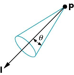
Thus to create a spotlight we need to specify the position of the light, the direction in which the light is pointing, and how wide the cone of illumination is. We set the position parameter similarly to point lights, and set the direction parameter using the command
glLightfv(source, GL_SPOT_DIRECTION, *dir);
where source is the source and dir is a 3 element array containing a vector direction (NOT a "look at" point).
The width of the cone is specified by a cutoff angle that is set by the command
glLightf(source, GL_SPOT_CUTOFF, angle);
where source is the source and angle is the angle of the light cone projecting from the light's position in the light's direction.
Finally we can control how the light intensity varies across the cone so that objects near the axis of the cone appear to be illuminated more brightly than objects near the edge of the cone using an attenuation exponent (which is computed similarly to the shininess coefficient for materials). The default value for the exponent is 0 which produces uniform illumination throughout the illumination area. Positive values will produce brighter illumination at the center (directly in front of the light) and weaker illumination towards the boundary of the light cone. NOTE: Be careful when making very focused spotlights (e.g. a "laser pointer") as the geometry of the scene may not have sufficient detail to render the point effect. Also remember that if your light (or material) has no specular components, the spotlight may have little to no effect. The spotlight exponent is set using the command
glLightf(source, GL_SPOT_EXPONENT, exp);
where source is the source and exp is the spotlight attenuation exponent.
In lighting.h is a utility function that will set all the parameters for a spot light
void set_SpotLight(GLenum source, LightType *light, GLfloat *position
                   GLfloat *dir, GLfloat cutoff, GLfloat exp);
which takes as arguments the source that we want to set, a LightType structure by reference for the color channels, a position array for the location of the spotlight, a dir array for the direction the spotlight is pointing, a cutoff angle for the cutoff angle, and an exp for the attenuation exponent. (Note there is also a function named set_SpotLightAttenuated( ) that takes additional attenuation parameters to create an attenuated spotlight source.)
Tasks
Add code to lighting.h to create a LightType called red_light using the following properties
- Ambient - (0.1,0.1,0.1,1.0)
- Diffusive - (1.0,0.0,0.0,1.0)
- Specular - (1.0,0.8,0.8,1.0)
Define global variables light1_pos[ ], light1_dir[ ], light1_cutoff, and light1_exp to (0,2,0,1), (0,-1,0), 90, 0 to create a spotlight with a 90 degree uniform illumination cone located on the y axis pointing in the -y direction.
Add code to render_Scene( ) to make GL_LIGHT1 a red_light spotlight source using the four variables defined in the previous step.
3. Vertex Normals
In the last lab we defined the normals for an entire surface, i.e. the normals for each vertex defining a surface were identical. This produces a uniform lighting effect across the surface and is useful for small surfaces where the variation of the surface orientation with respect to the light is negligible. However, for larger surfaces or ones with significant contour, having a continuously varying normal across the surface produces a more realistic effect. This is accomplished by setting different normals per vertex that the graphics pipeline will interpolate across the surface. Thus just like when different colors are set per vertex (which is essentially what varying the normal does) the resulting effect will be a gradient shading of the surface depending on which vertex normals are pointing more directly at the light source.
Tasks
- Define the global variable vnormals[ ][3] such that the components are the same as the corresponding vertex coordinates. Essentially we are defining an "average" normal based on the intersecting faces and as such this is NOT a general procedure. NOTE: These normals are not unit normals, however our shader takes care of normalization.
- Add code to vquad( ) to pass the appropriate normal into the pipeline (using glNormal3fv( )) prior to passing each vertex (since the normal is set for subsequent vertices).
4. Shader Light Sources
Much of the computations for point and spot light sources is similar to directional lighting, except now we will need to compute the l vector as the difference between the light source position and the vertex (giving a vector pointing from the vertex to the light source). Also for spotlights, we will need to determine if the vertex is inside the cone of illumination for the spotlight and apply any attenuation depending on where in the cone the vertex falls. Note that we will assume the viewer is far away and thus can set a default eye vector. For more accurate lighting effects, we can compute the eye position (known as a local viewer).
Tasks
Add code to lightvert.vs in main( ) to transform the vertex position to eye coordinates ecPosition by multiplying by just gl_ModelViewMatrix and normalizing by the homogeneous coordinate.
// Transform vertex to eye coordinates
ecPosition = gl_ModelViewMatrix * gl_Vertex;
ecPosition3 = (vec3(ecPosition)) / ecPosition.w;
Add code to lightvert.vs in the PointLight( ) function to compute the light direction vector VP, the magnitude of VP (for attenuation computations), and then normalize VP.
// Compute vector from surface to light position
VP = vec3(gl_LightSource[i].position) - ecPosition3;

// Compute distance between surface and light position
d = length(VP);

// Normalize the vector from surface to light position
VP = normalize(VP);
Add code to lightvert.vs in the SpotLight( ) function to again compute the light direction vector VP similarly to the point light function
// Compute vector from surface to light position
VP = vec3(gl_LightSource[i].position) - ecPosition3;

// Compute distance between surface and light position
d = length(VP);

// Normalize the vector from surface to light position
VP = normalize(VP);
Add code to lightvert.vs in the SpotLight( ) function to compute the dot product spotDot between the light vector and the spotlight direction and then check if it is within the cutoff angle of the spotlight. If so, apply the spotlight attenuation exponent.
// Check if point on surface is inside cone of illumination
spotDot = dot(-VP,normalize(gl_LightSource[i].spotDirection));

if (spotDot < gl_LightSource[i].spotCosCutoff)
    spotAttenuation = 0.0; // not in spotlight cone
else
    spotAttenuation = pow(spotDot, gl_LightSource[i].spotExponent); // attenuate in cone

// Combine the spotlight and distance attenuation
attenuation *= spotAttenuation;
Compiling and running the program
Once you have completed typing in the code, you can build and run the program in one of two ways:
- Click the small green arrow in the middle of the top toolbar
- Hit F5 (or Ctrl-F5)
(On Linux/OSX: In a terminal window, navigate to the directory containing the source file and simply type make. To run the program type ./vertexNormalCube.exe)
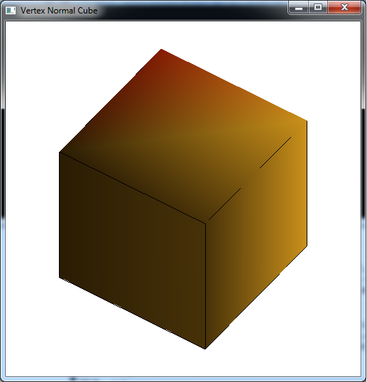
The output should look similar to below
To quit the program simply close the window.
While using vertex normals and additional light source effects improves the scene, it still does not appear quite realistic. This is most evident by what appears to be "bursting" of the light along the diagonals of the cube faces. This is an artifact of the large, flat surface being coarsely tesselated and thus having minimal geometry for the lighting effect. Unfortunately the only way to improve this situation is by adding additional geometry primarily to the flat surfaces (and accepting the resulting performance penalty that will be incurred). Rather than adding additional vertices manually, next time we will see how to automate the geometry generation through recursive subdivision which will dramatically improve the lighting effects (particularly for spotlights).
