Last lab we created geometry by hand which was cumbersome to say the least. Usually a 3D modeling program (such as Blender) is used to create complex object geometries (and apply textures, etc.) which are then loaded into the DirectX application using a model loader. The loader will import the geometry into a Mesh class object which we can then render. This lab will create a basic mesh framework that will import vertex positions and colors (subsequent labs will extend this class to include materials and textures). Note we will be using Luna's .m3d file format which is not a format generated by standard modelling programs but rather is simple to parse to understand how the various pieces of a model are used. Ultimately we would want to use a more sophisticated model loader and/or write a converter from a standard format (such as .obj) to Luna's format.
0. Getting Started
Download CS470_Lab05.zip, saving it into the labs directory.
Double-click on CS470_Lab05.zip and extract the contents of the archive into a subdirectory called CS470_Lab05. Place this subdirectory into the Documents/Visual Studio 2013/Projects directory.
Navigate into the CS470_Lab05 directory and double-click on CS470_Lab05.sln (the file with the little Visual Studio icon with the 12 on it) which should immediately open Visual Studio with the project.
If the Header Files, Resource Files and Source Files folders in the Solution Explorer pane are not expanded, expand each by double clicking on them and double-click on M3DMesh.h, M3DMesh.cpp, BasicMeshApp.h and BasicMeshApp.cpp.
The Vertex.h file contains declarations for the vertex structure (similar to the one in the Cube class from last lab) as well as the matching layout description.
struct MeshVertex {
    XMFLOAT3 pos;
    XMFLOAT4 color;
};
1. M3DMesh Declaration
Double-click M3DMesh.h which should have a skeleton structure already in the file with the method prototypes already in place.
We will first add the class attributes (variables) in the public section. The first attributes are simply local copies of the mesh data for manipulation by the application. Often mesh objects contain multiple subsets of data which define sections of the mesh that use different materials (although for now we will only use a single material, i.e. colors, for the entire mesh). We also have a MeshGeometry attribute which will handle the creation of the various DirectX buffers and render the object. Lastly we will store a local transformation matrix for the object.
// Local Mesh data copies
std::vector<MeshVertex> Vertices;
std::vector<USHORT> Indices;
std::vector<MeshGeometry::Subset> Subsets;

UINT SubsetCount;

// Mesh geometry and local instance transformation
MeshGeometry MeshData;
XMFLOAT4X4 World;
2. Mesh Definition
Double-click M3DMesh.cpp which should have a skeleton structure already in the file with stubs for some of the methods. The first three methods are standard constructor/destructor methods.
Initialization
This method will create the mesh object by loading the data from the specified file which will parse the .m3d file format as defined by Luna (note: this is not a standard 3D model format). Then the method will use the MeshGeometry object to create the necessary vertex and index buffers from the data.
loadM3DMesh(modelFilename);

MeshData.SetVertices(device, &Vertices[0], Vertices.size());
MeshData.SetIndices(device, &Indices[0], Indices.size());
MeshData.SetSubsetTable(Subsets);

// Store number of subsets for rendering
SubsetCount = SubSets.size();
Reading .m3d Files
Parsing the (basic) .m3d file format in loadM3DMesh() is straightforward as the file contains header information followed by three sections for the subset table, vertex data, and index data. Recall that all the geometry will be constructed from triangles.
// Open .m3d mesh file
std::ifstream fin(modelFilename);

if (fin)
{
    fin >> ignore;                 // ignore file header text
    fin >> ignore >> numVertices;  // read number of vertices
    fin >> ignore >> numTriangles; // read number of triangles

    // Read mesh data
    ReadSubsetTable(fin, 1); // only one material for now
    ReadVertices(fin, numVertices);
    ReadTriangles(fin, numTriangles);

    return true;
}
The individual section methods are likewise straightforward as they begin with a header line followed by entries for the data that we parse into individual items in the corresponding data vectors.
First we read the subset data which defines which vertex and index blocks each material will use (since we only have a single material, there will only be one subset containing all the vertices and indices).
// Read subset table
fin >> ignore; // ignore subset header text

// Read subset data
for (UINT i = 0; i < numSubsets; ++i)
{
    fin >> ignore >> Subsets[i].Id;
    fin >> ignore >> Subsets[i].VertexStart;
    fin >> ignore >> Subsets[i].VertexCount;
    fin >> ignore >> Subsets[i].FaceStart;
    fin >> ignore >> Subsets[i].FaceCount;
}
The .m3d file then contains a list of all the vertices for the entire object. Again the section simply begins with a header followed by lines containing the position coordinates and the color channels.
fin >> ignore; // ignore vertices header text

// Read vertex data
for (UINT i = 0; i < numVertices; ++i)
{
    fin >> ignore >> Vertices[i].pos.x >> Vertices[i].pos.y >> Vertices[i].pos.z;
    fin >> ignore >> Vertices[i].color.x >> Vertices[i].color.y >> Vertices[i].color.z >> Vertices[i].color.w;
}
Finally we load the (triangle) indicies by ignoring a header and looping through all the triangles to parse out the respective indices.
fin >> ignore; // ignore triangles header text

// Read index data for all triangles
for (UINT i = 0; i < numTriangles; ++i)
{
    fin >> Indices[i * 3 + 0] >> Indices[i * 3 + 1] >> Indices[i * 3 + 2];
}
Once all the data is loaded, the various methods for the MeshGeometry object are called to create the corresponding buffers similar to how they were created in the last lab.
Draw
Drawing is handled by the MeshGeometry class by again setting the appropriate buffers, telling DirectX what type of primatives to use (triangles), and then rendering an entire subset which for now is the entire object.
3. BasicMeshApp Definition
Again our application will be a subclass of D3DApp similar to previous labs. This time we will add a class attribute for our mesh object (and corresponding filename).
// Cube mesh object
M3DMesh mBox;
std::string mMeshFileName;
4. BasicMeshApp Declaration
In our application class source BasicMeshApp.cpp, we will add the mesh filename to the constructor
mMeshFileName = "cube.m3d";
Then we just need to add initialization in the Init() method after loading the shader via the base class Init().
// Call cube object initialization
mBox.Init(md3dDevice,mMeshFileName);
Finally in DrawScene() we simply need to draw the mesh by setting the view-projection matrix and looping over all the subsets.
// Render object
// Set modelview projection matrix for object
XMMATRIX w = XMLoadFloat4x4(&mBox.World);
XMMATRIX wvp = w*VP;
mFXMatVar->SetMatrix(reinterpret_cast<float*>(&VP));
// Draw subsets
for (UINT subset = 0; subset < mBox.SubsetCount; ++subset)
{
    mTech->GetPassByIndex(p)->Apply(0, md3dImmediateContext);
    mBox.MeshData.Draw(md3dImmediateContext, subset);
}
4. Compiling and running the program
Once you have completed typing in the code, you can build and run the program in one of two ways:
- Click the small green arrow in the middle of the top toolbar
- Hit F5 (or Ctrl-F5)
The output should look similar to below
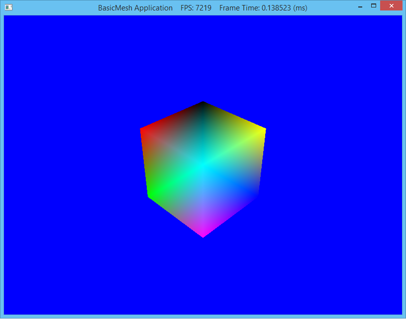
To quit the program simply close the window.
If we wish to use different vertex layouts and/or shaders per mesh we could move buildFX() and buildVertexLayouts() into the mesh class and then set the layout each time every mesh is rendered. However, since eventually we will be using a standard mesh format which will include lighting and texture fields, it will be more efficient to set it once in the application and then simply render all the meshes with the same layout.
While the mesh model format is marginally easier to use than creating geometry natively in a class, it would still be extremely cumbersome for even moderately complex geometry. Fortunately most 3D modeling programs can export the models to a standard DirectX format (.x). While DXUT includes a loader for this format, standard DirectX does not.
