Now that we render geometry with both lighting and texture mapping, we will explore a nice way to organize the objects into our scene, particularly those that have a direct relationship to each other. For example, the position of your hand is related to the position of your arm which is related to the position of your body. Thus rather than having to continually recompute the absolute position of each part, we would like to create a mechanism for simply keeping track of the relative positioning of each part with respect to the other parts. Therefore, when one part moves, e.g. your body, those parts connected to it will automatically move with it. We can accomplish this by constructing a tree structure known as a scene graph. In the scene graph, every object will become a node which will contain the local transformations for that particular object as well as any necessary rendering components. The tree then provides a convenient mechanism for preserving the transformations from level to level, hence objects that are related will have the same transformations applied to them automatically. Once the tree has been constructed, rendering the scene is simply a matter of traversing the tree using a depth first approach (actually any part of the tree can likewise be rendered by starting at the desired node). This structure allows for simple addition/removal of nodes from the scene by manipulation of the relationships between the nodes. Also note that in this lab we will employ multiple shaders such that some nodes will be illuminated by lighting while others will be texture mapped.
Getting Started
Navigate into the CS370\labs directory on your H: drive.
Download CS370_Lab14.zip, saving it into the labs directory.
Double-click on CS370_Lab14.zip and extract the contents of the archive into a subdirectory called CS370_Lab14
Open CLion, select Open or Import from the main screen (you may need to close any open projects), and navigate to the CS370_Lab14 directory. This should open the project and execute the CMake script to configure the toolchain.
Scene Graph Nodes
For the tree structure we will be using a child/sibling tree structure. The base node structure contains (among other things) two transformation matrices, pointers to connecting nodes, and an abstract draw method as follows:
    // Object properties
    vmath::mat4 BaseTransform;
	vmath::mat4 ModelTransform;
	BaseNode *sibling;
	BaseNode *child;

    virtual void draw(vmath::mat4 proj, vmath::mat4 cam, vmath::mat4 trans) = 0;
The BaseTransform will be the static transformation of the template object, e.g. scaling, and the ModelTransform will be the dynamic transformation that will include positioning relative to the parent node as well as any changing local transformations, e.g. variable rotation. The draw() method will take three matrices, proj which is the projection matrix, cam which is the camera matrix, and trans which is the parent’s dynamic transformation matrix.
Subclasses of BaseNode will then create specific implementations for different rendering mechanisms adding any additional fields and providing a concrete implementation of the draw() method. For example, MatNode will render objects using lighting and thus will have fields for the normals, lights, and materials to use in the draw() method. The subclass nodes also include various setter methods for these additional fields.
Note: For efficiency, the nodes only store references to the various buffer objects such that the same buffer data can be used by similar nodes.
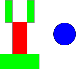
For this lab we will be constructing a simple robot with a circular base, a single lower arm, and two upper arms along with a separate spinning Earth sphere.
A diagram for the robot as a scene graph would be
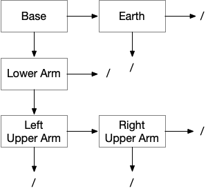
Note: Whenever a node does not have a child or sibling, its corresponding field should be set to NULL. A more general technique would be to dynamically allocate nodes as needed, i.e. similar to maintaining a linked-list, when the number of objects in the scene is variable (e.g. projectiles).
So for example the base node (assuming it is MatNode base with a lower arm node named MatNode lower_arm) could be created as follows
    base.set_shader(light_program, light_proj_mat_loc, light_camera_mat_loc, light_model_mat_loc);
    base.NormMatPtr = light_norm_mat_loc;
    base.set_buffers(VAOs[Cylinder], ObjBuffers[Cylinder][PosBuffer], light_vPos,
                     posCoords, ObjBuffers[Cylinder][NormBuffer], light_vNorm,
                     normCoords, numVertices[Cylinder]);
    base.set_materials(MaterialBuffers[MaterialBuffer], materials_block_idx,
                       Materials.size()*sizeof(MaterialProperties), material_loc,
                       MaterialIdx[Cylinder]);
    base.set_lights(LightBuffers[LightBuffer], lights_block_idx,
                    Lights.size()*sizeof(LightProperties), num_lights_loc,
                    Lights.size());
    base.set_eye(light_eye_loc, eye);
    base.set_base_transform(scale(vec3(BASE_RADIUS, BASE_HEIGHT, BASE_RADIUS)));
    base.sibling = NULL;
    base.child = &lower_arm;
Tasks
- Add code to build_scene_graph() to initialize the fields of the four nodes
- Base - Use the light_program shader and references using the set_shader() method, set the NormMatPtr field to the appropriate light shader reference, set the buffers to the Cylinder using the set_buffers() method, set the materials using the set_materials() method, set the lights using the set_lights() method, set the camera location using the set_eye() method, set the base transformation to scale the cylinder by BASE_RADIUS in x and z and BASE_HEIGHT in y using the set_base_transform() method, set the sibling pointer to NULL, and the child pointer to the lower arm. Hint: Use the code above as a starting point.
- Lower Arm - Construct the lower arm similar to the base but using the Cube index for the buffers and setting the base transformation to scale it to LOWER_WIDTH LOWER_HEIGHT and LOWER_DEPTH, then translate it in y by LOWER_HEIGHT (so it is positioned on the x-z plane), and make the child the left upper arm
- Upper Arms - Construct the upper arms similar to the lower arm but scaled by UPPER_WIDTH UPPER_HEIGHT and UPPER_DEPTH, then translated in y by UPPER_HEIGHT (so it is positioned on the x-z plane), and make the right upper arm a sibling of the left upper arm
Set empty node pointers to NULL and remember to use & to set the address of a connecting node to the pointer.
Local Transformation Updates
Once we have created the tree structure by setting the various node fields, we need to set the dynamic local transformation ModelTransform matrices for each piece to locate it relative to its parent using the update_transform() method inherited from the base class.
Note: We will need to call this method again whenever the local transformation needs updating, e.g. during animation or user input.
Tasks
- Add code to build_scene_graph() to update all the nodes. In particular:
- Base - rotate by angle theta about the y-axis.
- Lower arm - translate up by BASE_HEIGHT (to position it on top of the base) and rotate by angle phi about the x-axis.
- Upper arms - translate up by 2*LOWER_HEIGHT (to position it on top of the lower arm) and over in x by ±(LOWER_WIDTH + UPPER_WIDTH) (to position them on the left/right side of the lower arm) and rotate by angle left/right_psi about the x-axis.
- Add code to key_callback( ) to call the same update functions for the appropriate nodes when the user presses the corresponding keys. NOTE: This step is extremely important if you wish any user input to affect the scene
Rendering the Scene Graph
Finally we can render the scene by simply traversing the tree in a depth-first fashion starting at a root node using the traversal routine traverse_scene_graph() given by
void traverse_scene_graph(BaseNode *node, mat4 baseTransform) {
    mat4 model_matrix;

    // Stop when at bottom of branch
    if (node == NULL) {
        return;
    }

    // Apply local transformation and render
    model_matrix = baseTransform*node->ModelTransform;

    node->draw(proj_matrix, camera_matrix, model_matrix);

    // Recurse vertically if possible (depth-first)
    if (node->child != NULL) {
        traverse_scene_graph(node->child, model_matrix);
    }

    // Remove local transformation and recurse horizontal
    if (node->sibling != NULL) {
        traverse_scene_graph(node->sibling, baseTransform);
    }
}
Tasks
- Add a call to traverse_scene_graph() in render_scene( ) to render the scene. Make sure to pass the address of the root node, which in this case is base (i.e. you will need the & since the function parameter is a pointer).
Adding Other Objects to a Scene Graph
To place additional independent objects into a scene graph, we can simply make them siblings of the root node or and other sibling of the root.
Tasks
- Add code to build_scene_graph() to initialize the fields of the earth node such that it uses the tex_program shader and references using the set_shader() method, set the buffers to the Sphere using the set_buffers() method (make sure to use the TexBuffer rather than the NormBuffer index), set the TexID field to the Earth index of the TextureIDs[] array, set the base transformation to scale the sphere by 1.5f in all dimensions using the set_base_transform() method, and set the update tranformation to translate by 3.0f in y and 5.0f in z and rotate by earth_angle about the y axis
- Add code in build_scene_graph() to change the sibling of the base to the earth node
- Add code to main() in the render loop to update the transform after earth_angle has been updated
Note: This node is rendered using the TexNode class which has different fields and methods than the MatNode class as it is for rendering texture mapped nodes in the scene graph.
Compiling and running the program
You should be able to build and run the program by clicking the small green arrow towards the right of the top toolbar.
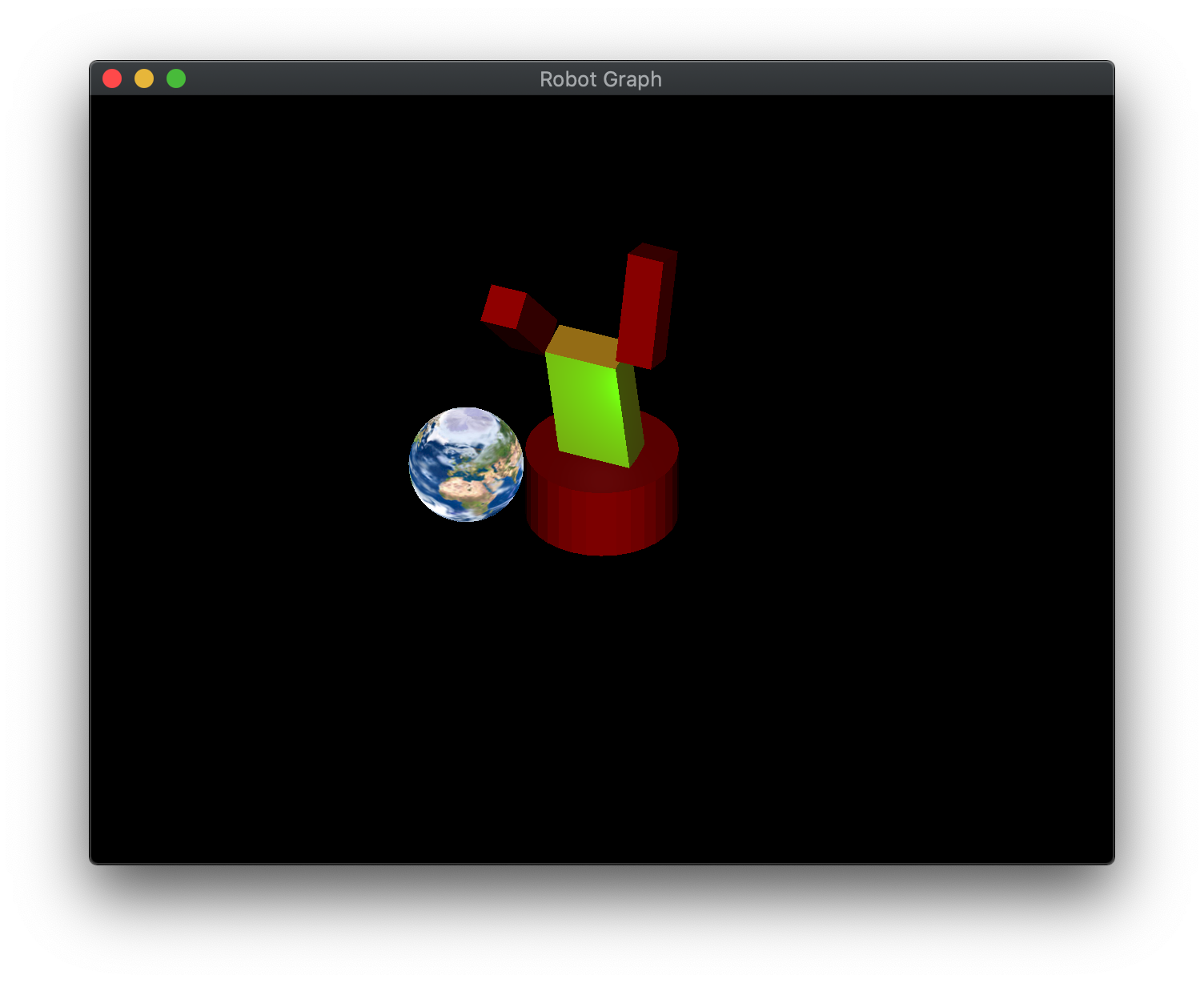
At this point you should see a robot with a spinning textured earth. You can manipulate the robot using a,d to rotate the base, w,s to rotate the lower arm, and n,m ,. to rotate the left/right upper arms. Note: Adjusting the robot does not affect the earth.
To quit the program simply close the window.
Congratulations, you have now written an application using a scene graph.
Next we will investigate how to add shadows into our scenes using a multipass rendering technique.
