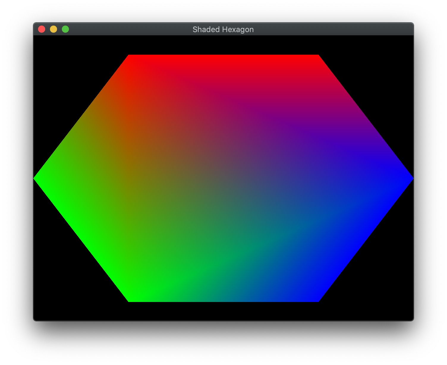
In the last lab we built some simple geometry and rendered it using a vertex buffer. However, the color of the rendered object was fixed (in the fragment shader). In OpenGL, we are able to define a color per vertex as an additional attribute along with the position. These colors will be similarly stored in a buffer and passed to the shaders. One nice property of the graphics system is that it will take care of bi-linearly interpolating colors between vertices thus creating a gradient fill effect automatically.
Getting Started
Download CS370_Lab02.zip, saving it into the CS370-Fall2022 directory.
Double-click on CS370_Lab02.zip and extract the contents of the archive into a subdirectory called CS370_Lab02
Open CLion, select CS370-Fall2022 from the main screen (you may need to close any open projects), and open the CMakeLists.txt file in this directory (not the one in the CS370_Lab02 subdirectory). Uncomment the line
add_subdirectory("CS370_Lab02" "CS370_Lab02/bin")
Finally, select Reload changes which should build the project and add it to the dropdown menu at the top of the IDE window.
Solution
Download CS370_Lab02_Solution.zip, saving it into the CS370-Fall2022 directory.
Double-click on CS370_Lab02_Solution.zip and extract the contents of the archive into a subdirectory called CS370_Lab02_Solution
Open CLion, select CS370-Fall2022 from the main screen (you may need to close any open projects), and open the CMakeLists.txt file in this directory (not the one in the CS370_Lab02_Solution subdirectory). Uncomment the line
add_subdirectory("CS370_Lab02_Solution" "CS370_Lab02_Solution/bin")
Finally, select Reload changes which should build the project and add it to the dropdown menu at the top of the IDE window.
Indexed Geometry
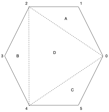
Since OpenGL uses triangles, i.e. faces, to render objects, for complicated objects vertices can be used by multiple faces. Rather than duplicate these vertices when we define the geometry, instead we will simply create a vector of unique vertices and then create a list of indices that specify which vertices to use for each face. Thus the elements of the indices vector will be ivec3, i.e. vectors consisting of three integer indices (triangles) for each face. In subsequent labs we will build geometry by loading models that represent objects in a similar fashion. Hence to create a hexagon, one possible tessellation, i.e. division into triangles is shown below
While OpenGL has a mechanism for drawing indexed geometry, we will build the vertex buffer by creating a temporary vector which stores all the vertices using a loop to unpack the faces (which will be similar to how we will eventually load models). While this format uses more memory, it will provide additional needed flexibility to specify different auxiliary attributes per face for the same vertex.
Tasks
-
Add code to build_hexagon() to define the indices vector (of type ivec3 with a list of vertex indices for each of the four triangles shown in the hexagon figure above. Note: Indices start at 0 and be sure to use proper orientation for each triangle.
-
Add code to build_hexagon() to set the obj parameter index for the numVertices array. Hint: There are 3 vertices per face.
Defining Colors
In OpenGL, colors are typically represented by four components in the range [0.0,1.0] - (r, g, b, a) - where r, g, and b are the red, green, and blue channels respectively, and a is the alpha channel which we will use later when we discuss alpha blending, i.e. transparency. While you may be familiar with the color channels being integers in the range [0,255] (for 24/32-bit colors), OpenGL provides a more flexible representation as a floating point number in the range [0.0, 1.0] which works with any color depth representation. Then OpenGL will convert the floating point number to a corresponding integer value per channel depending on the underlying system capabilities.
The interesting part about OpenGL colors is they are defined at each vertex. Thus, if vertices in the object have different colors, OpenGL’s default behavior is to perform bilinear interpolation to create a shaded gradient between the vertices.
Similarly to storing vertex coordinate data into a buffer, we will use the same commands to create and store the color data into a separate buffer.
Tasks
- Add code to build_hexagon() to define the colors vector (of type vec4) where the first vertex is blue, the next two vertices are red, the next two vertices are green, and the last vertex is blue (note for all colors we simply set the alpha channel to 1.0). For example, blue for the first vertex would be defined as
	// TODO: Define colors per vertex
	colors= {
		{0.0f, 0.0f, 1.0f, 1.0f},
	};
-
Add code to build_hexagon() to bind the HexGradient element from the ColorBuffers array. Hint: The Color_Buffer_IDs enum will contain a list of symbolic constants indexing the ColorBuffers array.
-
Add code to build_hexagon() to load data from the obj_colors vector into the color buffer. Hint: To get the size (in bytes) of the colors vector, use
sizeof(GLfloat)*colCoords*numVertices[obj]
i.e. the number of bytes in a GLfloat times the number of coordinates per color (which in this case is 4) times the number of vertices in the object (stored in the numVertices array). To get a pointer to the elements from the vector, use the .data() method. Finally, set the usage flag to GL_STATIC_DRAW (indicating that we will not be changing the vertices later on).
-
Add code to draw_color_object() to bind the color parameter element from the ColorBuffers array. Note: This structure will allow us to draw the same object with different colors.
-
Add code to draw_color_object() to associate the shader variable location stored in color_vCol, with colCoords coordinates per color (which is set to 4), that are of type GL_FLOAT, without normalization, no stride (since the data is tightly packed), and no offset using
glVertexAttribPointer(color_vCol, colCoords, GL_FLOAT, GL_FALSE, 0, NULL);
- Add code to draw_color_object() to enable the attributes using the shader location color_vCol using
glEnableVertexAttribArray(color_vCol);
- Add code to build_geometry() to call the build_hexagon() function passing the Hexagon constant.
Compiling and running the program
You should be able to build and run the program by selecting shadedHexagon from the dropdown menu and clicking the small green arrow towards the right of the top toolbar.
At this point you should see a gradient filled hexagon.
To quit the program simply close the window.
Congratulations, you have now rendered slightly more complex geometry.
Next we will learn how to manipulate our objects using transformations.
