We are now ready to begin rendering 3D scenes. Unlike 2D, which has a direct correlation between world coordinates and screen coordinates, we must project our 3D world onto a 2D screen. The quality of our scenes, however, will depend on preserving some degree of depth of the objects within the world. We can accomplish this through a variety of visual cues such as occlusion (objects being partially blocked by other objects), lighting (object surfaces displaying color gradients), and perspective (the closer the object is, the larger it appears).
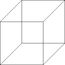
The simplest type of projection is known as orthographic, often used in engineering drawings. In this projection mode, the camera is assumed to be at an infinite distance, i.e. at +∞ looking in the -z direction. Thus all rays become parallel and objects will have the same height as they are in the world with parallel lines remaining parallel. For example, a cube drawn in orthographic projection would appear as (is the cube slanting downward to the left or upward to the right?)
Getting Started
Download CS370_Lab05.zip, saving it into the CS370-Fall2022 directory.
Double-click on CS370_Lab05.zip and extract the contents of the archive into a subdirectory called CS370_Lab05
Open CLion, select CS370-Fall2022 from the main screen (you may need to close any open projects), and open the CMakeLists.txt file in this directory (not the one in the CS370_Lab05 subdirectory). Uncomment the line
add_subdirectory("CS370_Lab05" "CS370_Lab05/bin")
Finally, select Reload changes which should build the project and add it to the dropdown menu at the top of the IDE window.
Solution
Download CS370_Lab05_Solution.zip, saving it into the CS370-Fall2022 directory.
Double-click on CS370_Lab05_Solution.zip and extract the contents of the archive into a subdirectory called CS370_Lab05_Solution
Open CLion, select CS370-Fall2022 from the main screen (you may need to close any open projects), and open the CMakeLists.txt file in this directory (not the one in the CS370_Lab05_Solution subdirectory). Uncomment the line
add_subdirectory("CS370_Lab05_Solution" "CS370_Lab05_Solution/bin")
Finally, select Reload changes which should build the project and add it to the dropdown menu at the top of the IDE window.
3D Geometry and the Depth Buffer
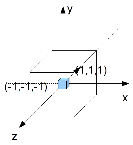
We define object geometry in 3D in the same manner as in 2D only now with each vertex having 3 components - (x,y,z). As a natural extension of our 2D world coordinate extents, in 3D space the extents of the rendered scene are [-1,1] for all three axes (we will change these extents later in this lab).
Unlike in 2D where objects were rendered via a Painter’s algorithm, i.e. the last object rendered is the one that appears, in 3D we typically want the closest object to be the one that appears. Fortunately, OpenGL provides a way of automatically performing this occusion behavior (also known as hidden surface removal since those surfaces that are hidden behind other ones are removed) through the use of the depth buffer. This buffer keeps track of the depth of the closest object for each rendered pixel. As subsequent objects are rendered, only those whos pixels have a depth less than the current closest one stored in the buffer are rendered (subsequently also updating the depth buffer accordingly). To use the depth buffer, we must enable the depth test (which in subsequent labs we will temporarily disable for effects like transparency) using the command (usually in main() with the other initializations)
glEnable(GL_DEPTH_TEST);
We must also clear the depth buffer every time we render the scene by adding the appropriate flag to the glClear() command at the beginning of the display() function
glClear(GL_COLOR_BUFFER_BIT | GL_DEPTH_BUFFER_BIT);
Finally, when we create 3D geometry, we must be careful to order our vertices properly. Each polygon we create will have a front face and a back face which is defined by the right-hand rule. If we curl the fingers of our right hand to follow the vertex order, our right thumb will point in the direction of the outward normal (i.e. the front face). Since typically our objects are solid, for efficiency we can tell OpenGL to not render, i.e. cull, back faces using
glEnable(GL_CULL_FACE);
Note: Later we will discuss viewing volumes, so if an object is partially clipped by the viewing volume, culling back faces will cause the entire object to disappear rather than rendering the back faces, i.e. inside surface, of our objects.
Tasks
-
Add code to main() to enable the depth buffer via the GL_DEPTH_TEST flag.
-
Add code to main() to enable back face culling via the GL_CULL_FACE flag.
-
Add code to display() to clear the depth buffer via the GL_DEPTH_BUFFER_BIT flag. What happens if you forget to do this?
-
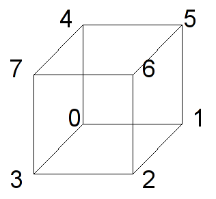
Add code to build_cube() to initialize the indices vector for all six faces based on the provided vertices which are shown in the figure below. Hint: You will need two triangles (with proper orientation) for each of the six faces, thus there should be 12 ivec3 sets of 3 indices (36 indices total).
At this point you should be able to render the scene but it may appear odd since the cube faces are as large as the view window. Note what happens if you do not enable the depth test or back face culling.
Orthographic Projection
Often it is convienient to define the geometry of the objects in our world without having to scale everything to fit within the default extents of [-1,1]. This will usually produce a visually poor scene (or nothing rendered at all). Thus we want to be able to adjust the viewing volume, i.e. the extents of our rendered world, so that the objects appear and fill the screen as we wish. For orthographic projection, the viewing volume will be a rectangular parallelapiped (rectangular “cube”) such that the default camera is at the origin looking down the z axis in the negative direction.
To change the extents, we will set the projection matrix by creating an orthographic viewing volume with our desired extents using
mat4 ortho(float left, float right, float bottom, float top, float near, float far);
where left and right are the x extents, bottom and top are the y extents, and near and far are the z extents. These values are measured from the camera whose default position is the origin (thus for now these values are the world extents).
Tasks
- Add code to display() to set proj_matrix to an orthographic projection with extents [-2.0,2.0] for all three axis.
You should now see the entire cube rendered in the center of the screen.
Resize callback
Observe that while we were able to see the entire cube after creating a larger orthographic viewing volume, the cube faces appear rectangular. This is due to the fact that while we have a cubical viewing volume, the aspect ratio of the window is not 1:1, i.e. it is wider than it is high. Thus objects will appear stretched in the horizontal direction. This is further exacerbated if the user decides to resize the window which will further distort the proportions of our rendered objects. This effect is known as isotropic scaling.
If, however, we would like our objects to maintain their original aspect ratios, e.g. squares remain square, we can add anisotropic scaling to our scenes through manipulation of the orthographic viewing volume extents based on the window dimensions. These dimensions can be queried using
void glfwGetFramebufferSize(GLFWwindow *window, int *width, int *height);
where window is the current window, and *width and *height are references to the current window size.
We can also retrieve these values whenever the user resizes the window through the framebuffer size callback which has the signature
void framebuffer_size_callback(GLFWwindow *window, int width, int height);
where window is the window being resized, and width and height are the new sizes of the window. We can register the framebuffer size callback in a similar fashion to the other callbacks using
glfwSetFramebufferSizeCallback(window, framebuffer_size_callback);
where window is the reference to the current window and framebuffer_size_callback is the name of the resize callback routine.
Thus if we store the window sizes in global variables when the window is initially created and anytime the user resizes the window, we can adjust our orthographic viewing volume accordingly to have a similar aspect ratio using
	// Adjust viewing volume (orthographic)
	GLfloat xratio = 1.0f;
	GLfloat yratio = 1.0f;
	// If taller than wide adjust y
	if(ww <= hh)
	{
		yratio = (GLfloat) hh/ (GLfloat) ww;
	}
	// If wider than tall adjust x
	else if (hh <= ww)
	{
		xratio = (GLfloat) ww/ (GLfloat) hh;
	}
	proj_matrix = ortho(-1.0f*xratio,1.0f*xratio,-1.0f*yratio,1.0f*yratio,-1.0f,1.0f);
Tasks
-
Add code to main() to get the initial window sizes storing the results in ww and hh
-
Add code to framebuffer_size_callback() to update ww and hh with the width and height parameters
-
Add code to main() to register the framebuffer_size_callback resize callback
-
Add code to display() to create an anisotropic orthographic projection matrix and store it in proj_matrix
Now observe the shape of the cube as you change the aspect ratio of the window.
Compiling and running the program
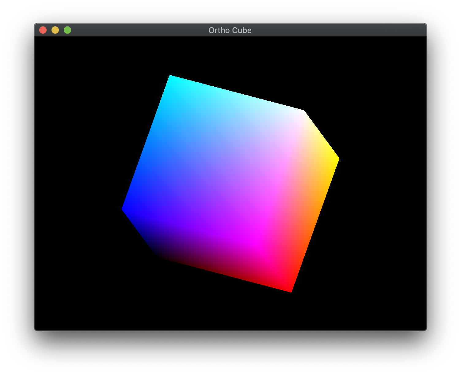
You should be able to build and run the program by selecting orthoCube from the dropdown menu and clicking the small green arrow towards the right of the top toolbar.
At this point you should see a spinning cube with gradient colored faces.
To quit the program simply close the window.
Congratulations, you have now rendered your first 3D scene with an orthographic projection.
Next we will discuss how to load models rather than build geometry manually, create a perspective projection, and place a camera in the scene.
